http://lolofi.blogspot.com/2015/02/four-quadrant-wave-multiplier-ring.html
Stretch out the jack leads so they can be soldered to the board


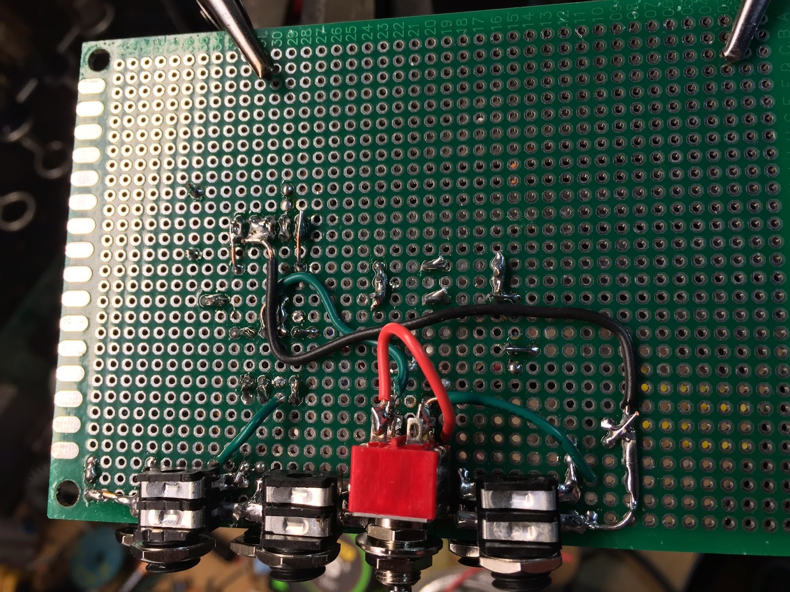
This is the ground wire that is connected to all the jacks


Continue adding all the jacks. Notice here that I short the ground to switched side of the jacks. These will disconnect the ground to the 'tip' of the jack when a cable is plugged in.


Now the jacks are on I add the headers and the chip.

I solder the DPDT directly to the board by bending two of the connections. I also have the wires that I'll connect pushed through the other side and wound on onto these two terminals to give it a little more support. This will eventually be held in a metal front panel so i'm not that worried about it breaking off.

Below is how the eurorack header should be soldered on the underside.

Here are the completely populated boards. Ready to sound check.

The board is a little to big for a eurorack so i use a Dremel to cut it back.


Getting ready to construct the front panel
For getting the holes right on the front panel I take a sheet of paper and place it over the module. I then shine a light under it so that i can better see the where the jacks are aligned. I then mark each hole with a pen.


This will be my drill pattern that I can take to my metal sheets to drill. Front panels will be a different topic i'll post later on.
No comments:
Post a Comment