Wednesday, February 11, 2015

Four Quadrant Wave Multiplier / Ring Modulator with Distortion Feedback (Part 2)

This will just cover some of the pictures of the build of the last project:

http://lolofi.blogspot.com/2015/02/four-quadrant-wave-multiplier-ring.html


Stretch out the jack leads so they can be soldered to the board


This is the ground wire that is connected to all the jacks


Continue adding all the jacks. Notice here that I short the ground to switched side of the jacks. These will disconnect the ground to the 'tip' of the jack when a cable is plugged in.


Now the jacks are on I add the headers and the chip.


I solder the DPDT directly to the board by bending two of the connections. I also have the wires that I'll connect pushed through the other side and wound on onto these two terminals to give it a little more support. This will eventually be held in a metal front panel so i'm not that worried about it breaking off.


Below is how the eurorack header should be soldered on the underside.


Here are the completely populated boards. Ready to sound check.


The board is a little to big for a eurorack so i use a Dremel to cut it back.


Getting ready to construct the front panel


For getting the holes right on the front panel I take a sheet of paper and place it over the module. I then shine a light under it so that i can better see the where the jacks are aligned. I then mark each hole with a pen.


This will be my drill pattern that I can take to my metal sheets to drill. Front panels will be a different topic  i'll post later on.


Four Quadrant Wave Multiplier / Ring Modulator with Distortion Feedback (Part 1)

This has to be the one of the simplest and most useful modules I've built for my eurorack. The name makes it sound really complicated and I guess it could be if you built it from scratch but I'm using these Analog Devices AD633 chips that do it all for you.

Basic Operation

It simply multiplies two signals together and the '4 quadrants' come from the fact that it has both inverting and non inverting inputs for each channel. Therefore you get (X1 - X2) * (Y1 - Y2).  

This chip also has additional summing input (Z). You can mix another signal into the output of the multiplier or you can feed it back into its self. Always a crowd pleaser. 

So What Does it Really Do?

Like I said before this is really good utility module. It can do a lot of things depending on how you wire it. For example:
  • Voltage Controlled Amplifier
  • Tremelo
  • Ring Modulator
  • Wave Doubler (in Theory .. harder in practice)
  • Voltage Controlled Mixer (kinda.. this is a stretch)


Here is my basic circuit diagram. If you just want a basic Wave Multiplier then do this. You need a resistor, the AD633 and some switched jacks. The switched jacks ensure that 0 volts is going into the inputs if no signal is plugged in.

I wanted a little more interesting sound so I built this distortion feedback circuit that can be enabled with a DPDT switch. This overdrives the amplifier and provides clipping with the diodes.

Below is how the EuroRack Power header is to be wired.


This whole project can be built in a few hours for less than 50 USD. Here is the parts list:

   6 - S6/BB Mono Switched 3.5mm Jack Panel Mount Solder Tag (Euro Rack Sized)
   1 - AD633
   1 - Circuit Board - 2200 Holes - 160 x 115mm
   1 - Switch DPDT
   4 - Diodes
   1 - 10 Pin EuroRack Power Header


Here it is in operation

I first start using the Maths as a Envelope Generator and use the circuit as a VCA. Later on I increase the speed and it transitions from tremolo to ring modulation. Then you can use another LFO to subtract signals from each other to create beating frequencies. There is also some switching of the feedback switch to add gain and clipping (distortion). Enjoy and let me know what you think.

Next post will show more details on the build of the project.

Wednesday, February 4, 2015

Using the Arduino UNO as a Guitar Pedal


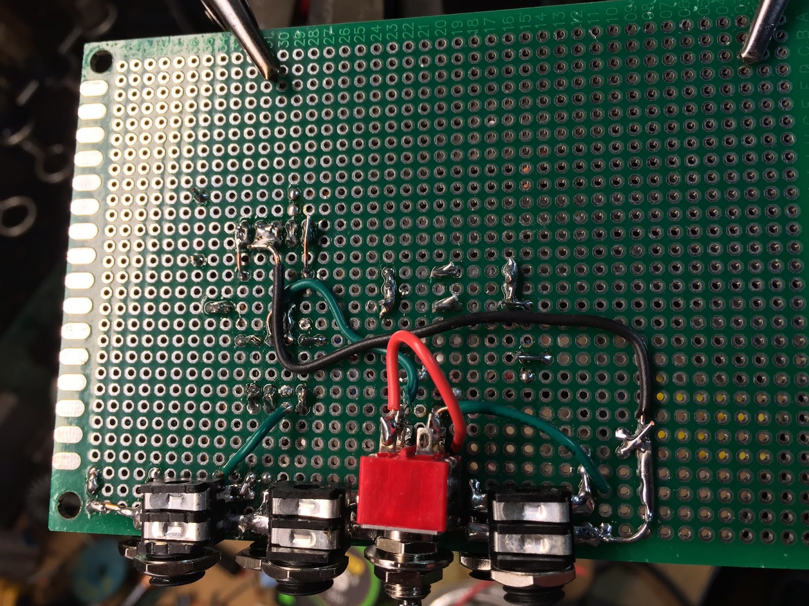
This is a project a built a few years ago and I almost lost the code to it so i'm going to archive it here. I built a really lowfi bitcrushing guitar pedal using the Arduino UNO. There were a lot of challenges with this because the ADC's are and processor are slow and there are not true digital to analog outputs. This cannot be done with the Arduino UNO alone and needs some supporting circuits around it. Mainly a SPI Digital to Analog Converter and a DC offset circuit on the input. (Remember from a previous post that the ADC's cannot read negative voltage so you have to boost it up on a DC signal.)

You can get the full code Here: Arduino UNO Guitar Pedal

I'm not going to cover in detail most of the peripheral circuits since most people will customize this if you do build it. The main thing i'll cover though is the MCP4911 DAC. Here is how to wire the DAC. I recommend getting one of the Arduino developer shields to do this project.


You need to also build a DC offset for the input. I used an opamp designed for single supply projects (LM358).This looks like the following and it's output goes into A0 on the UNO.
R1 and R4 = 1k
R2 = Trim Pot - I used a trim pot to get the right dc offset.
R3 = I think i just put this to GND on mine.
VCC = The 5V source from the Arduino.

Now for the Arduino code.

There is a lot of code to get this project working so i'm going to step through it bit by bit. Click Here for the Full Code. I'll start with the ADC code in the setup function. For speed i'm only doing 8 bit conversions. Most of this code is borrowed from other blogs. This was so long ago i can't remember where i got it (Maybe HERE)but i don't take credit for creating all of this. I may have tweeked it a bit. Below is my setup function. This is using the Timers library to trigger samples.


#include <spi .h=""> #include <timerone .h=""> #define cbi(sfr, bit) (_SFR_BYTE(sfr) &amp;= ~_BV(bit)) #define sbi(sfr, bit) (_SFR_BYTE(sfr) |= _BV(bit)) volatile unsigned int input; //Analog input volatile unsigned int pot1; //stored value of the Left Potentiometer volatile unsigned int pot2; //stored value of the Right Potentiometer volatile boolean newSample=false; // new sample check volatile byte ibb; //used to force a slight delay on the ADAC conversions. volatile byte LSW; //store the value of the left momentary switch volatile byte RSW; //store the value of the right momentary switch int LED = 2; // Led to indicate if the effect is on or off int LeftSW=4; //left momentary foot switch input int RightSW=3; //right momentary foot switch input boolean RightDown=false; boolean LeftFown=false; boolean RightToggle = false; boolean LeftToggle = false; void setup() { Serial.begin(115200); pinMode(10, OUTPUT); pinMode(8,OUTPUT); pinMode(LED,OUTPUT); pinMode(RightSW, INPUT); pinMode(LeftSW, INPUT); digitalWrite(8, LOW); // set adc prescaler to 64 for 19kHz sampling frequency cbi(ADCSRA, ADPS2); sbi(ADCSRA, ADPS1); sbi(ADCSRA, ADPS0); cbi(ADMUX,ADLAR); // 8-Bit ADC in ADCH Register cbi(ADMUX,REFS0); // VCC Reference sbi(ADMUX,REFS1); cbi(ADMUX,MUX0); // Set Input Multiplexer to Channel 0 cbi(ADMUX,MUX1); cbi(ADMUX,MUX2); cbi(ADMUX,MUX3); // Timer2 PWM Mode set to fast PWM cbi (TCCR2A, COM2A0); sbi (TCCR2A, COM2A1); sbi (TCCR2A, WGM20); sbi (TCCR2A, WGM21); cbi (TCCR2B, WGM22); // Timer2 Clock Prescaler to : 1 sbi (TCCR2B, CS20); cbi (TCCR2B, CS21); cbi (TCCR2B, CS22); Timer1.initialize(33); // ~= 15k*2 Hz Timer1.attachInterrupt( Sample ); SPI.begin(); SPI.setBitOrder(MSBFIRST); SPI.setDataMode(SPI_MODE0); } </timerone></spi>
This code sets up the SPI interface for the DAC as well as all the prescalers for the ADC. Its a little complicated if your new to the Arduino but you can copy and past this and it should work.

Next we have the sample function. Notice this is referenced in setup by the Timer to trigger this function once the intercept happens. Once the timer interval runs it will start sampling the ADACs. The sample function also samples the Audio on every other intercept. Audio is sampled on the first intercept; The next intercept will sample the knob values. The two knobs are not sampled at the same time but every other time as well. The sequence is defined below in the comments. You can get away with this since the knobs don't need to have the same sample rate as the audio. By doing it this way each knob is sampled at half the frequency of the audio.

///The Sample Interrupt Function /// THis function does all the sampling. /// I have Two knobs on this effect pedal that can control /// different parameters. All together i'm using Three analog /// inputs. This code is a little hacked but i'll describe what /// I'm doing here: /// 1) I read the audio input every other time the sample is triggered /// 2) I read the knob input every time the sample is not being read. /// The knobs are alternated as well when it comes to reading. /// Example Sequence: /// intercept1 : Audio input is read /// intercept2 : Knob 1 is read /// intercept3 : Audio input is read /// intercept4 : Knob 2 in read. /// .... /// /// volatile boolean samplesw = true; volatile boolean potsw=false; boolean isFirst=true; void Sample(){ if(samplesw){ samplesw=false; input = ADCL; input = input | (ADCH &lt;&lt; 8); if(potsw) sbi(ADMUX,MUX0); // read Pot1; B000 B001 else sbi(ADMUX,MUX1); newSample=true; }else { samplesw=true; if (potsw){ potsw=false; pot2 = ADCL; pot2 = pot2 | (ADCH &lt;<8 0="" analog="" b000="" b010="" back="" before="" cbi="" conversion="" delay="" digital="" else="" ibb--="" ibb="" inputs="" leftsw="" lsw="(PIND" next="" pot1="pot1" potsw="true;" read="" rightsw="" rsw="(PIND" sbi="" set="" short="" start="" to="" xmp=""> I have two monetary switches and two knobs on my pedal. That means I need 3 analog inputs and two digital ones. This is the reason for the following global variables. You may assign your inputs on different pins. <xmp> volatile unsigned int input; //Analog input volatile unsigned int pot1; //stored value of the Left Potentiometer volatile unsigned int pot2; //stored value of the Right Potentiometer volatile boolean newSample=false; // new sample check volatile byte ibb; //used to force a slight delay on the ADAC conversions. volatile byte LSW; //store the value of the left momentary switch volatile byte RSW; //store the value of the right momentary switch int LED = 2; // Led to indicate if the effect is on or off int LeftSW=4; //left momentary foot switch input int RightSW=3; //right momentary foot switch input boolean RightDown=false; boolean LeftFown=false; boolean RightToggle = false; boolean LeftToggle = false;

Right Switch Code

I use the right momentary footswitch to turn the effect on an off. Almost a True bypass but i use an analog mutliplexer(MUX) which allows me to route the guitar input either into the Arduino or straight to the output. Most people would want to use a DPDT to achieve a true bypass but at the time I didn't have one laying around. I did however have a ton of analog multiplexers I bought off ebay to build an analog sequencer while back. If you choose to use the DPDT switch then you can leave off the Right Switch global above and the effectOn Code below. The Switch code will send the proper binary signal to the MUX to switch it to position one or two.

Below is the Right momentary switch Code. Notice I add delays to the code. This is to prevent bounce when the switch is initially pressed. Bounce happens when the contacts on the switch are just starting to touch. This can cause the switch to read on and off several times before finally resting. The delays prevents this and basically says "i don't care what the switch reads until the timeout is reached". ///Effect Switch Check /// Checks the button to see if the effect has been turned on. /// There is some delay times added here with the 'now' and 'rwait' variables. /// This to prevent the arduino from reading multiple presses while the switch /// is initially being pressed. When you first press the switch it can connect /// and disconnect multiple times right as the internal connections are being /// made. This will cause the pedal to be un predictable at selecting the next /// effect. /// Parameters: /// * now - The current time in milliseconds. This is to ensure delay to prevent bounce. int last=0; int rwait=0; boolean rdown=0; void effectOn(int now){ last = now; if(RSW == LOW &amp;&amp; (now - rwait) &gt; 15000){ //Serial.println("Down"); rwait = now; if(!rdown){ //Serial.println("Toggle"); RightToggle=!RightToggle; rdown=true; } }else if(RSW &gt; 0 &amp;&amp; (now - rwait) &gt; 15000 &amp;&amp; rdown){ //Serial.println("UP"); rdown=false; } if(RightToggle)// 76543210 PORTD = PORTD | B00100100; else PORTD = PORTD &amp; !(B00100100); }

Left Switch Code

And Here is the Left monetary FootSwitch Code. I use this to switch between different effects i've programmed in. //Effect Select... iterate though effects. /// There is some delay times added here with the 'now' and 'lwait' variables. /// This to prevent the arduino from reading multiple presses while the switch /// is initially being pressed. When you first press the switch it can connect /// and disconnect multiple times right as the internal connections are being /// made. This will cause the pedal to be unpredictable at selecting the next /// effect. /// Parameters: /// * NumEfct - The number of effects that are programmed minus 1. If you have 3 effects then this number should be 2. /// * now - This is the current time in milliseconds. This is to ensure delay to prevent bounce. int selected=0; int llast; int lwait; int ldown; int effectSelect(int NumEfct, int now){ llast = now; if(LSW == LOW &amp;&amp; (now - lwait) &gt; 15000){ //Serial.println("Down"); lwait = now; if(!ldown){ //Serial.println("Toggle"); LeftToggle=!LeftToggle; ldown=true; selected++; } }else if(LSW &gt; 0 &amp;&amp; (now - lwait) &gt; 15000 &amp;&amp; ldown){ //Serial.println("UP"); ldown=false; } if(selected &gt; NumEfct) selected =0; return selected; }

DAC Code

Next is the DAC code. This code works on the MCP4911 to send audio via SPI to the DAC. I use the built in Arduino SPI library for this. ///Write to DAC /// i use an external DAC and use the SPI out to write to it. /// The chip i use is the MPC4911 void writecmd(unsigned int value){ //digitalWrite(10,LOW); // 76543210 PORTB = PORTB &amp; !(B00000100); // set low int data = (value) &lt;&lt; 2; // The 4911 has certain bits that need to be set at the most significant bits. These are: // 0|1 write vs ignore // 0|1 unbuffered vs buffered // 0|1 2X gain vs no gain // 0|1 shutdown vs active mode // 0x7000 will give me write + buffered + 2x gain + active mode data = 0x7000 | data; //Serial.println(data, BIN); SPI.transfer(data&gt;&gt;8); //transfer the first 8 bits SPI.transfer(data); // transfer the last 8 bits //digitalWrite(10,HIGH); PORTB = PORTB | (B00000100); // set High }

Main Loop

Now we have the main Loop. All we need to do here is wait for a new sample and then process it. I always use the Left pot (pot1) to change effect parameters and the right pot (pot2) to change the gain. //Main Loop void loop() { while(!newSample); int now = micros(); newSample=false; effectOn(now); int sw = effectSelect(2, now); unsigned long output = 0; input = input * ((10 * pot2)/1023); // Change input gain if(sw==0){ output = sampleAndHold(input , pot1); //output=input; } else if(sw == 1){ output=andDistortion(input, pot1); } writecmd(output); }

Finally The Effects!!!

Later at the end of my code I Add all the effects: ///Effects //// Effect 0: Sample and Hold /// Used to lower the sampling rate int sah_i=0; int sah_hold; int sampleAndHold(int input, int holdTime){ int ht = holdTime/10; if(sah_i==0){ sah_hold=input; sah_i++; }else if(sah_i &lt; ht){ sah_i++; }else if(sah_i &gt;= ht){ sah_i=0; } return sah_hold; } //Effect 1: Logic Function distortion // This just does a logical AND with the Hex value in the array /// Use once of the knobes to change the value that will be anded /// the input. int crush[] = {0x3FF, //0 0x0EE,//1 0x0DD,//2 0x0BB,//3 0x077,//4 0x0CC,//5 0x099,//6 0x033,//7 0x066,//8 0x088,//9 0x011,//10 0x022,//11 0x044};//12 int andDistortion(int input, int selector){ int c = selector*20/1023; //Serial.println(c); return input&amp;crush[c]; } ///Effect 2: Sample and Hold with LFO /// Used to change the sample rate at the rate of the LFO /// Nothing new to add here since we are using effect0 plus some supporting functions //+++++++++++++++++++++++++++++++++++++++++++++++ //supporting functions //triangle LFO int samp=0; int sr=15000; int lfo_skip=0; int lfo_hold=0; int LFO(int _skip){ if(lfo_skip == 0){ lfo_hold++; lfo_skip++; if(lfo_hold &gt;= 100){ lfo_hold=0; } }else{ lfo_skip+=_skip+1; if(lfo_skip &gt;= 1000){ lfo_skip=0; } } //Serial.println(lfo_skip); return lfo_hold; }

The Power

The Arduino UNO has an onboard voltage regulator that can take at least 9volts DC. I added a normal BOSS power connector to the pedal and wired it as follows so that i can just plug it into my power chain with the rest of my guitar pedals.

THe USB Connector

I drilled a 3/8in hole on the side to allow me to reprogram it at anytime. Its just big enough to get the connector to the board.

Resources

Arduino UNO Full Code
MCP4911 DAC
Single Supply OpAmps
Analog Multiplexers
LoFi Guitar Pedal-Instructables

Thursday, January 29, 2015

Building a Joystick Controller


Recycling old joysticks for synths.

I modified this old joystick controller to give me an X-Y control over some of my synth parameters. I use this a lot with my MS-20 where X controls High Pass and Y controls the lowpass. This project is super easy to build and these old joysticks are generally pretty cheap on ebay or thrift stores. 


Details:
  • IN - Any input signal. You can feed in straight DC signal or output from an LFO. You can even use it a just a simple attenuator since thats really all it its.
  • X- the x axis output
  • Y- the y axis output
  • B - Black button output
  • R - Red button output
Things needed:
  • An old analog joystick
  • 2 resistors
  • A small breakout box. (easy found at radio shack)
  • A soldering iron.
The operation of IN, X, and Y should be obvious. B and R are just like triggers. They send 0 volts out until the button is pressed and then emits what your receiving on the IN. This works pretty well but i need to replace the switches on mine. They are old and don't work so well.


Here is how to rewire it (the header on the right represents the striped end of the joystick controller):
  1. Cut off the connector end of the joystick and strip the wires out.
  2. Find the wire that will be your IN. This is usually a red wire and would have previously been wired to the power pins. You may need to use a volt meter to find this. The Power wire will be wired to one end of both of the joystick pots and the GND will be wired to the other end. Center pins of the pots are the outputs.
  3. Find the Ground wire. This one is usually black.
  4. In your breakout box start connecting the Ground wire is on the sleeves of all the jacks in your breakout box.
  5. Wire each jack's tip to the proper wire as shown above.
  6. I added two 100k Resistors to the inputs of each button (this could be anything really. I just had them laying around though 1k would be better i guess). These are solely to ensure that the IN does not go to ground for any reason when the buttons are pressed. Wire them as in the diagram below.

Mine looks like this:

The big green wire above connected to the resistors is  added by me  to bridge the IN wire back around to these resistors. The IN (red) wire is connected to one end of both potentiometers in the joystick controller.


That's pretty much it!. 


Here is how it sounds. Button pressing changes the pitch so that it sounds kinda like an arpeggiator. X and Y are connector the the CVs of the High and Low pass inputs.


Wednesday, January 28, 2015

BitCrushing with the Arduino

Now that I have the previous examples working fairly easily its time to do some more interesting effects with the Arduino due. Time to make a bit crusher! This blog will be all about downsampling the input signal in real time. This creates an effect called aliasing. Aliasing happens when then audio frequency being processed is below the Nyquist rate. It creates really grainy distorted sounds. I personally love this effect. I like digital effects that try to sound digital but hate digital effects that try to sound analog.


Here is the code:


#define MAX_ADC_RESOLUTION 12 void setup() { // Serial.begin(9600); REG_ADC_MR = (REG_ADC_MR &amp; 0xFFF0FFFF) | 0x00020000; analogReadResolution(MAX_ADC_RESOLUTION); // analogWriteResolution(MAX_ADC_RESOLUTION); //adc_init(ADC, SystemCoreClock, ADC_FREQ_MAX*2, 3); pinMode(ADC0,INPUT); pinMode(DAC0,OUTPUT); } void loop() { int value = sampleAndHold(analogRead(ADC0), lfo()); analogWrite(DAC0, value); } int i=0; int hold; int sampleAndHold(int input, int holdTime){ if(i==0){ hold=input; i++; }else if(i &lt; holdTime){ i++; }else if(i &gt;= holdTime){ i=0; } return hold; } int _lfo=0; int wait=0; int lfo(){ if(wait==0){ _lfo++; wait++; if(_lfo &gt;= 500){ _lfo=0; } }else{ wait++; if(wait &gt;= 1000){ wait=0; } } return _lfo; } Above a created a really simple sawtooth LFO to change the sample rate time. This controls the rate of the sampleAndHold function that basically stores and replays previous samples until the holdTime is reached. Once the holdTime is reached it samples again and will continue replaying the new sample. Here is what it sounds like:

Tuesday, January 27, 2015

Arduino Due Audio Tests


I have had this Arduino due for a while and have wanted to make a music project out of it. It has been hard to find any really good examples of using this thing for audio. I finally found these few sites that have helped me speed up the ADC conversions so they are good for audio.

http://forum.arduino.cc/index.php?topic=156849.0

http://www.djerickson.com/arduino/


So from those two posts I was able to build these two projects and I'm overall impressed with the results:


Simple Audio Delay with Feedback

Note that the ADC's only track ~0-3V and most audio signals go negative  (example: -1V to 1V). You will mostly likely need to add a DC offset to your input to avoid clipping the signal. (cutting off the lower half of the waveform). You can do this in many of different ways. I happen to have some modular synth gear and one module in particular is the MATHS by Make Noise. I use this to amplify and offset the input signal. In a later post I might build a circuit to perform the DC offset. They are very simple but right now I want to just do some simple tests without spending too much time if it sounds terrible. For now here is an image of a DC offset amplifier:


Here is the code to create a very simple audio delay with feedback using the Arduino Due. Not all of this code will run on other Arduino's as they might be to slow or not have enough memory and setting of the ADC registers is specific to this version.


#define MAX_ADC_RESOLUTION 12 #define L 20000 int array[L]; // audio buffer to store previous input levels. This makes the delay line. int p=0; int d=0; void setup() { Serial.begin(9600); REG_ADC_MR = (REG_ADC_MR &amp; 0xFFF0FFFF) | 0x00020000; analogReadResolution(MAX_ADC_RESOLUTION); analogWriteResolution(MAX_ADC_RESOLUTION); adc_init(ADC, SystemCoreClock, ADC_FREQ_MAX*2, 3); pinMode(ADC0,INPUT); pinMode(DAC0,OUTPUT); } void loop() { int value = analogRead(ADC0) + array[p]; analogWrite(DAC0, value); array[p++]=value&gt;&gt;1; // bit shift to fade out over time if(p &gt; L) p=0; }
Here is an example of what it sounds like. Not bad but there is a lot of room for improvement. The noise is the first issue that needs to be addressed. I found that this comes from the delay line and I will most likely need to add some type of filter to overcome this.


If you take the loop function above and change it to just the following code then this will simply pass the signal through without modification. Notice that the signal output is much cleaner.


void loop() { int value = analogRead(ADC0); analogWrite(DAC0, value); }
In my next post I will try to clean this up. But for right now this at least gets me started.

LFO for CV Control 

The below application uses a potentiometer on A0 to control the speed of the LFO. One end of the pot is tied to the 3.3 V header, center is tied to A0, and the other end is tied to GND. This is just a test as this is a terrible CV controller since the output only goes to about 3 volts while most CV signals can get up to 10 volts. I may try to put an amplifier on the end to get the voltage to real CV levels.


#define MAX_ADC_RESOLUTION 12 void setup() { REG_ADC_MR = (REG_ADC_MR &amp; 0xFFF0FFFF) | 0x00020000; analogReadResolution(MAX_ADC_RESOLUTION); adc_init(ADC, SystemCoreClock, ADC_FREQ_MAX*2, 3); pinMode(DAC0,OUTPUT); pinMode(ADC0,INPUT); } int i=0; void loop() { int val = analogRead(ADC0); analogWrite(DAC0, sinx(val)); } float sinx(int skip){ float x = (125.0*sin(2*PI*i/90000.0))+125.0; // 125.0 is my DC offset. You need to get the sine wave so it does not ever go negative or it will clip i=i+skip/125+1; // The 125 in this skip is arbitrary and not at all related to the dc offset. if(i &gt;= 90000) i=0; return x; } Below is the board i use for these projects:
Arduino Due

Thursday, January 15, 2015

Hello World

Welcome to lolofi. This blog will be my site for archiving DIY kits I've built for my own modular synths and guitar effects. These rage from simple electronic circuits with just one or two chips to some Arduino audio projects I've put together. There are a few circuit bent projects I use as well. This site will mostly archive those projects cause I've been terrible at keeping up with my own notes and research in my journals.

Let me explain where I'm coming from when it comes to making music. I like to experiment. I've been striving to create a tone and layering of sounds that is unique. I care far less about a player's ability than how they put the pieces together. A song with 3 chords can be more inspirational to me that someone that can play overly complex arrangements without a glitch. I also tend to like music that is not overly produced and you can hear the imperfections. No auto-tune for me!

My current setup involves a few modular synths, analog and digital drum machines, an arsenal of guitar pedals, feedback loops, and some software that lets me do almost infinite guitar loops live. I'll share more about this set up later since several of the effects I use are all DIY and can be built in a few hours at most with very little electronics background.