Here is the code:
Showing posts with label effects. Show all posts
Showing posts with label effects. Show all posts
Wednesday, January 28, 2015
BitCrushing with the Arduino
Now that I have the previous examples working fairly easily its time to do some more interesting effects with the Arduino due. Time to make a bit crusher! This blog will be all about downsampling the input signal in real time. This creates an effect called aliasing. Aliasing happens when then audio frequency being processed is below the Nyquist rate. It creates really grainy distorted sounds. I personally love this effect. I like digital effects that try to sound digital but hate digital effects that try to sound analog.
Here is the code:
#define MAX_ADC_RESOLUTION 12
void setup() {
// Serial.begin(9600);
REG_ADC_MR = (REG_ADC_MR & 0xFFF0FFFF) | 0x00020000;
analogReadResolution(MAX_ADC_RESOLUTION); //
analogWriteResolution(MAX_ADC_RESOLUTION);
//adc_init(ADC, SystemCoreClock, ADC_FREQ_MAX*2, 3);
pinMode(ADC0,INPUT);
pinMode(DAC0,OUTPUT);
}
void loop() {
int value = sampleAndHold(analogRead(ADC0), lfo());
analogWrite(DAC0, value);
}
int i=0;
int hold;
int sampleAndHold(int input, int holdTime){
if(i==0){
hold=input;
i++;
}else if(i < holdTime){
i++;
}else if(i >= holdTime){
i=0;
}
return hold;
}
int _lfo=0;
int wait=0;
int lfo(){
if(wait==0){
_lfo++;
wait++;
if(_lfo >= 500){
_lfo=0;
}
}else{
wait++;
if(wait >= 1000){
wait=0;
}
}
return _lfo;
}
Above a created a really simple sawtooth LFO to change the sample rate time. This controls the rate of the sampleAndHold function that basically stores and replays previous samples until the holdTime is reached. Once the holdTime is reached it samples again and will continue replaying the new sample.
Here is what it sounds like:
Here is the code:

Tuesday, January 27, 2015
Arduino Due Audio Tests
I have had this Arduino due for a while and have wanted to make a music project out of it. It has been hard to find any really good examples of using this thing for audio. I finally found these few sites that have helped me speed up the ADC conversions so they are good for audio.
http://forum.arduino.cc/index.php?topic=156849.0
http://www.djerickson.com/arduino/
So from those two posts I was able to build these two projects and I'm overall impressed with the results:
Simple Audio Delay with Feedback
Note that the ADC's only track ~0-3V and most audio signals go negative (example: -1V to 1V). You will mostly likely need to add a DC offset to your input to avoid clipping the signal. (cutting off the lower half of the waveform). You can do this in many of different ways. I happen to have some modular synth gear and one module in particular is the MATHS by Make Noise. I use this to amplify and offset the input signal. In a later post I might build a circuit to perform the DC offset. They are very simple but right now I want to just do some simple tests without spending too much time if it sounds terrible. For now here is an image of a DC offset amplifier:

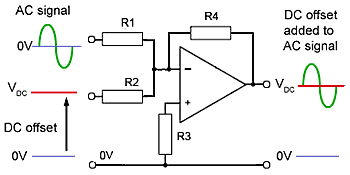
Here is the code to create a very simple audio delay with feedback using the Arduino Due. Not all of this code will run on other Arduino's as they might be to slow or not have enough memory and setting of the ADC registers is specific to this version.
Here is an example of what it sounds like. Not bad but there is a lot of room for improvement. The noise is the first issue that needs to be addressed. I found that this comes from the delay line and I will most likely need to add some type of filter to overcome this.
If you take the loop function above and change it to just the following code then this will simply pass the signal through without modification. Notice that the signal output is much cleaner.
In my next post I will try to clean this up. But for right now this at least gets me started.
LFO for CV Control
The below application uses a potentiometer on A0 to control the speed of the LFO. One end of the pot is tied to the 3.3 V header, center is tied to A0, and the other end is tied to GND. This is just a test as this is a terrible CV controller since the output only goes to about 3 volts while most CV signals can get up to 10 volts. I may try to put an amplifier on the end to get the voltage to real CV levels.

Subscribe to:
Posts (Atom)