Showing posts with label soldering. Show all posts

Wednesday, February 11, 2015

Four Quadrant Wave Multiplier / Ring Modulator with Distortion Feedback (Part 2)

This will just cover some of the pictures of the build of the last project:

http://lolofi.blogspot.com/2015/02/four-quadrant-wave-multiplier-ring.html


Stretch out the jack leads so they can be soldered to the board


This is the ground wire that is connected to all the jacks


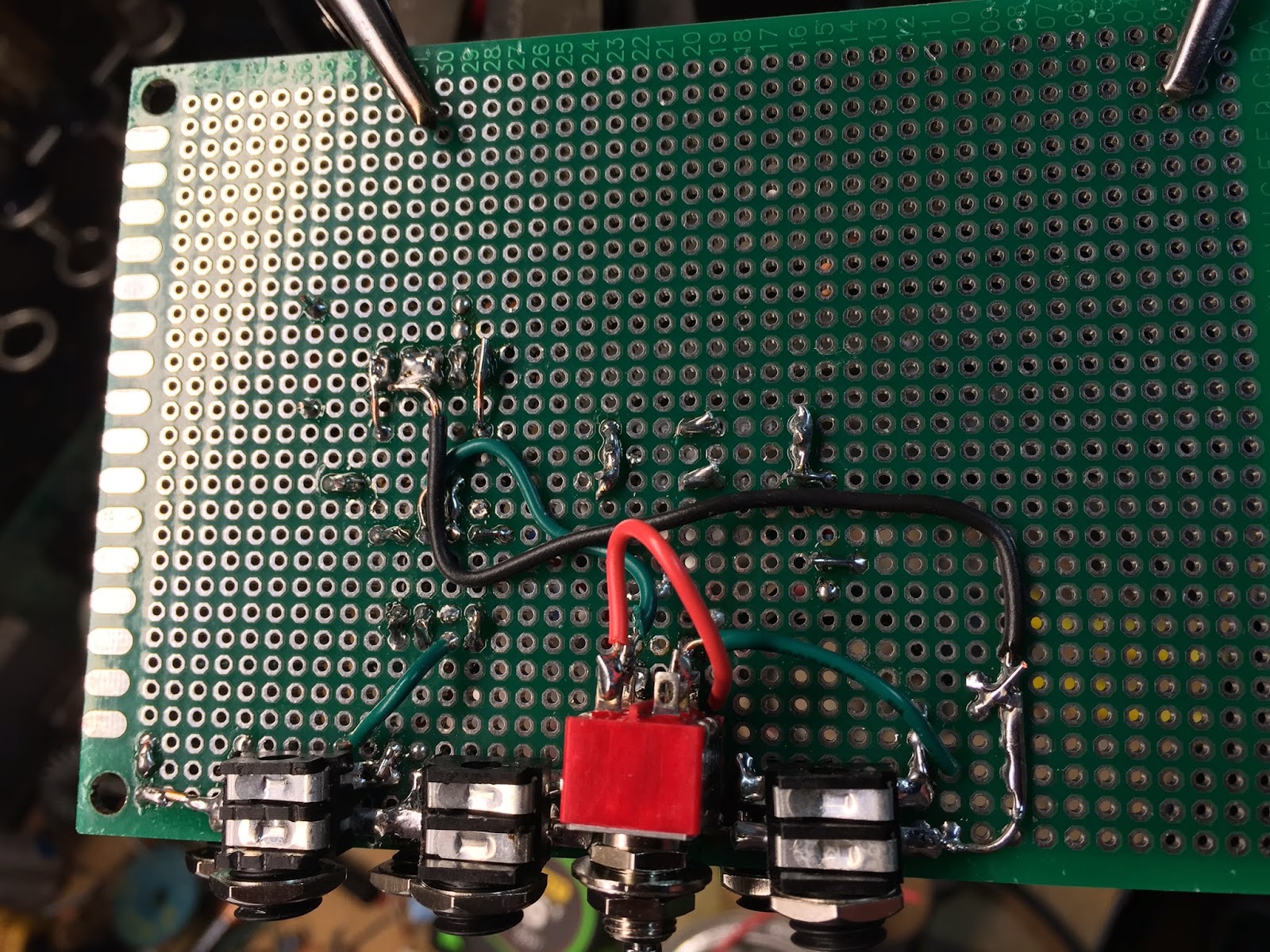
Continue adding all the jacks. Notice here that I short the ground to switched side of the jacks. These will disconnect the ground to the 'tip' of the jack when a cable is plugged in.


Now the jacks are on I add the headers and the chip.


I solder the DPDT directly to the board by bending two of the connections. I also have the wires that I'll connect pushed through the other side and wound on onto these two terminals to give it a little more support. This will eventually be held in a metal front panel so i'm not that worried about it breaking off.


Below is how the eurorack header should be soldered on the underside.


Here are the completely populated boards. Ready to sound check.


The board is a little to big for a eurorack so i use a Dremel to cut it back.


Getting ready to construct the front panel


For getting the holes right on the front panel I take a sheet of paper and place it over the module. I then shine a light under it so that i can better see the where the jacks are aligned. I then mark each hole with a pen.


This will be my drill pattern that I can take to my metal sheets to drill. Front panels will be a different topic  i'll post later on.


Four Quadrant Wave Multiplier / Ring Modulator with Distortion Feedback (Part 1)

This has to be the one of the simplest and most useful modules I've built for my eurorack. The name makes it sound really complicated and I guess it could be if you built it from scratch but I'm using these Analog Devices AD633 chips that do it all for you.

Basic Operation

It simply multiplies two signals together and the '4 quadrants' come from the fact that it has both inverting and non inverting inputs for each channel. Therefore you get (X1 - X2) * (Y1 - Y2).  

This chip also has additional summing input (Z). You can mix another signal into the output of the multiplier or you can feed it back into its self. Always a crowd pleaser. 

So What Does it Really Do?

Like I said before this is really good utility module. It can do a lot of things depending on how you wire it. For example:
  • Voltage Controlled Amplifier
  • Tremelo
  • Ring Modulator
  • Wave Doubler (in Theory .. harder in practice)
  • Voltage Controlled Mixer (kinda.. this is a stretch)


Here is my basic circuit diagram. If you just want a basic Wave Multiplier then do this. You need a resistor, the AD633 and some switched jacks. The switched jacks ensure that 0 volts is going into the inputs if no signal is plugged in.

I wanted a little more interesting sound so I built this distortion feedback circuit that can be enabled with a DPDT switch. This overdrives the amplifier and provides clipping with the diodes.

Below is how the EuroRack Power header is to be wired.


This whole project can be built in a few hours for less than 50 USD. Here is the parts list:

   6 - S6/BB Mono Switched 3.5mm Jack Panel Mount Solder Tag (Euro Rack Sized)
   1 - AD633
   1 - Circuit Board - 2200 Holes - 160 x 115mm
   1 - Switch DPDT
   4 - Diodes
   1 - 10 Pin EuroRack Power Header


Here it is in operation

I first start using the Maths as a Envelope Generator and use the circuit as a VCA. Later on I increase the speed and it transitions from tremolo to ring modulation. Then you can use another LFO to subtract signals from each other to create beating frequencies. There is also some switching of the feedback switch to add gain and clipping (distortion). Enjoy and let me know what you think.

Next post will show more details on the build of the project.

Thursday, January 29, 2015

Building a Joystick Controller


Recycling old joysticks for synths.

I modified this old joystick controller to give me an X-Y control over some of my synth parameters. I use this a lot with my MS-20 where X controls High Pass and Y controls the lowpass. This project is super easy to build and these old joysticks are generally pretty cheap on ebay or thrift stores. 


Details:
  • IN - Any input signal. You can feed in straight DC signal or output from an LFO. You can even use it a just a simple attenuator since thats really all it its.
  • X- the x axis output
  • Y- the y axis output
  • B - Black button output
  • R - Red button output
Things needed:
  • An old analog joystick
  • 2 resistors
  • A small breakout box. (easy found at radio shack)
  • A soldering iron.
The operation of IN, X, and Y should be obvious. B and R are just like triggers. They send 0 volts out until the button is pressed and then emits what your receiving on the IN. This works pretty well but i need to replace the switches on mine. They are old and don't work so well.


Here is how to rewire it (the header on the right represents the striped end of the joystick controller):
  1. Cut off the connector end of the joystick and strip the wires out.
  2. Find the wire that will be your IN. This is usually a red wire and would have previously been wired to the power pins. You may need to use a volt meter to find this. The Power wire will be wired to one end of both of the joystick pots and the GND will be wired to the other end. Center pins of the pots are the outputs.
  3. Find the Ground wire. This one is usually black.
  4. In your breakout box start connecting the Ground wire is on the sleeves of all the jacks in your breakout box.
  5. Wire each jack's tip to the proper wire as shown above.
  6. I added two 100k Resistors to the inputs of each button (this could be anything really. I just had them laying around though 1k would be better i guess). These are solely to ensure that the IN does not go to ground for any reason when the buttons are pressed. Wire them as in the diagram below.

Mine looks like this:

The big green wire above connected to the resistors is  added by me  to bridge the IN wire back around to these resistors. The IN (red) wire is connected to one end of both potentiometers in the joystick controller.


That's pretty much it!. 


Here is how it sounds. Button pressing changes the pitch so that it sounds kinda like an arpeggiator. X and Y are connector the the CVs of the High and Low pass inputs.